Random 3D Modeling

  • Thread starter Thread starter lumberjack
  • Start date Start date
  • Replies Replies 42
  • Views Views 5K

lumberjack

Young man on the go
Joined
Mar 6, 2005
Messages
9,796
Location
Mississippi
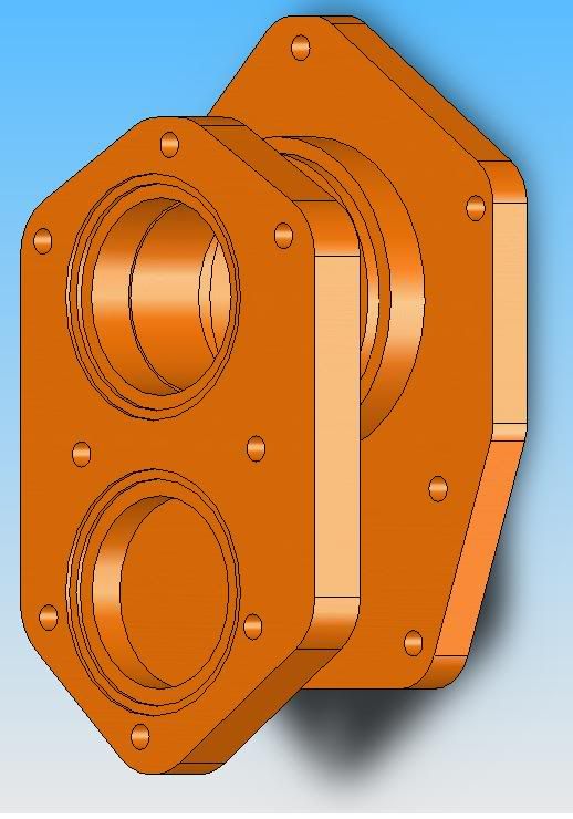
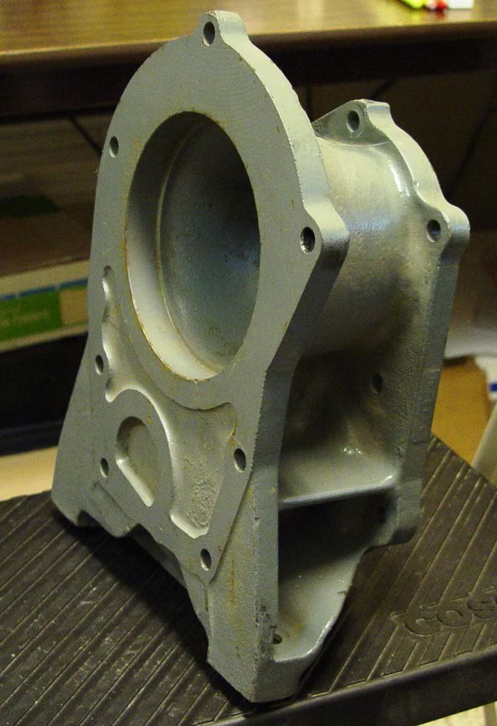
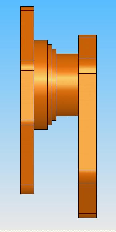
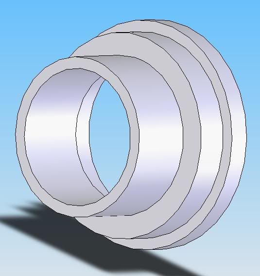
This is a rare adapter, produced by GM between 1973-1975. It mounts the SM465 transmission with the NP 203 transfer case as shortly as possible.

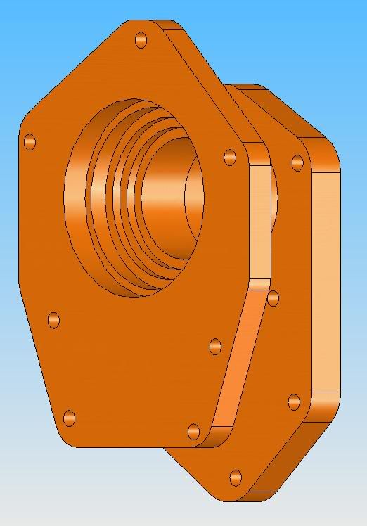
The notch in the top hole, and the D shaped blind hole will be added when I get the measurements off the tranny.

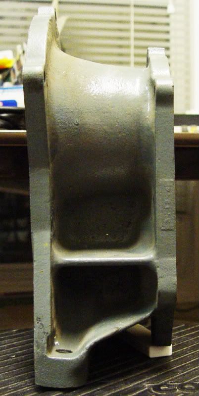
The one made from plate and tubing is 2lbs heavier before welding than the cast version. The cross tube can be made a number of ways, and the mounting would be left to the discretion of the end user of the adapter.

Accuracy to +/- .005".

DSC05374.jpg

Adapter465Side.jpg


DSC05372.jpg

Adapter203Side.jpg


DSC05375.jpg

AdapterSideView203onLeft.jpg
 
Your drawings are fine and dandy Carl, but how many pieces do you plan to machine that out of? What machine, and how much time do you have to spend on that machine, do you plan to use?
You also missed the mounting bolts to the tranny mount in your drawing.

You could do the machining with a ball mill. long reach, on a five axis with 260deg travel, most have 40deg travel.
You could do it on a seven axis lathe milling it, it would be to out of balance to turn at realistic RPMs to turn it.
You could make it out of three pieces, pressed and pined/bolted together, but you loose strength fast that way.
Everything on that can be made/done on a Bridgeport mill, BUT NOT the way it is drawn. You are thinking like an engineer. I think engineers need at least 5 years machining before they can draw a blueprint so they have a clue how to make it.
 
  • Thread Starter Thread Starter
  • #5
WOW, Andy.... wow. Better call the coroner because my head is so far up my arse that there's no way it's getting out before I die from asphyxiation.


The whole thing can be made with a bench top drill press, porta band/hacksaw/plasma/oxy-fuel torch, and welder. With enough determination you could do it with a hand drill and a welder. It uses common sized metal for easier access.

And if you look back, I detailed my reasoning regarding the mounting foot.

Well color me an asshole!!

The mount is a "discrection", my bad.

The +/-.005 isn't off the shelf or portaband teritory though.

Sorry, I'll STFU and go back to my corner.
 
Why are you taking the class? What do you expect to gain?


-Scott.
 
I'd love to take a machine course. I was around that stuff a lot a s a kid but I never learned much about it. I was the torch flunky, I just cut and painted stuff.

It does seem that adapter would be best produced by casting rather than machining. You should make one of these...
Warner_3.jpg


Warner precision rifle sight for high power competition. I have this one for sale by the way.
 
  • Thread Starter Thread Starter
  • #13
Out of steel it would be bomb proof.

Yep, the materials list is:
8"x.75"x10.5" flat bar
6"x1"x10" flat bar
Additional 6" length of either, modeled for 6"x1"

1/4" wall round tube:
5"x.75"
3.5"x1.75"

how much was the course?

$320 at the community college

...It does seem that adapter would be best produced by casting rather than machining...

If the production run was large enough, sure. That's what GM did. The drawing I did has an accurate bolt pattern put into steel with the idea of making the pieces and welding them together.

Like this:

http://cgi.ebay.com/SM-465-NP-205-A...uck_Parts_Accessories?_trksid=p3286.m20.l1116

The advantage is it's hella strong, doesn't get destroyed when an input shaft dies, is easily made from readily available materials, and offers the end user more adjustability and mounting options.

The adapter in the pictures cost me $250, about $25 less than market price at the time. It's at least 10 years older than me, has already spent one life in a truck somewhere, and it's still cast.

I didn't think about 4.5"x.25" round tube not being common, so here is the revised cross tube. A piece of 5"x.25" tube, a piece of 3.5"x.25" tube, and the adapter is made from a piece of flat bar.

AdapterNewCrosstube.jpg


...You should make one of these...

Warner precision rifle sight for high power competition. I have this one for sale by the way.

Haha I could model it, but I don't have the equipment to make it, yet ;)

Frans, AA doesn't make this adapter, their adapters are aluminum, expensive as hell, and not easily modified.

The materials for this adapter, as modeled, is about $50.
 
The problems I forsee going this way Carl, are there are a lot of joints, those create weak spots, more joints, more weak spots.
Machined from a solid block of Alum. (VERY expensive, I get that) would be much stronger. Steel better yet, but a lot more labor intensive.
For SAG's it would be a GREAT learning experiance, learing tolerance fits and machining principals.
 
I once had a hand in doing the same thing that you are pursuing, Carl, on a number of projects. The fellow I worked with was from the old school and used nothing but calipers, compasses and double measurements. He was 92 and his machine shop run on belts and shafts.

From old broken castings we fabricated machined and welded replicas.

My high school metal shop had more advance tools, but the work that man produced with his old machines was impeccable and accurate.
 
You can do just about anything on a manual machine as on a CNC .It just takes about 10 times as long .

My dad blowed a transfer case out one time on a hopped up Chevy 3/4 ton with a souped up 350 ,Holly double pumper ,lift kit ,the whole nine yards .Couldn't find another ,any where .I glued about 15 pieces back together with about 2-3 pounds of nickle rod ,put new bearings in it and as far as I know it's still working . At any rate the old man ran it about another 4 years before he sold it .
 
Hi Carl
What cad program are you using?

With what you have draw you will have more stack up tolerances then +/- .005.
as i see it you have 3 peace to make. 1 top plate, 1 round midle peace 1 bottom plate with welding then together. If you bar stock tolerance is at +/- .005 now you should use S7 or A2 for straingth. The middle pease should be the same size for ease of machine.
When designing thing try to only add in features that you need.

You can send me drawing' to me to look then over to see if there are thing you could do deferent. I not saying what you have is bad just things can be done to make it ease to make.
I'm a designer by trade 10 year's in. I work with tool shops, mold maker & stamping die maker all day long.

Travis
 
You can do just about anything on a manual machine as on a CNC .It just takes about 10 times as long .

I second that Al. Here's my current project solid modeled in Autocad 2008 and it will be completely machined on a knee-mill and engine lathe:
 

Attachments

  • Hodgson 9 Cylinder Radial.jpg
    Hodgson 9 Cylinder Radial.jpg
    71.7 KB · Views: 3
  • Hodgson 9 Cylinder Radial Cutaway.jpg
    Hodgson 9 Cylinder Radial Cutaway.jpg
    85 KB · Views: 1
  • Subassembly - Crankshaft.jpg
    Subassembly - Crankshaft.jpg
    77 KB · Views: 1
  • Subassembly - Cylinder1.jpg
    Subassembly - Cylinder1.jpg
    80.8 KB · Views: 1
Hi tblough
That look cool. How long to design that in autocad.
I've been on solidworks for 2 years & ashlar for 7 years, 9 year with 3d molding.
Travis
 
Her is what I'm working on . The 1st pic is a bench tester for eng.
the 2nd & 3thr are crank sensor's for Cadillaca 4.0l

Travis
 

Attachments

  • (dis tester).jpg
    (dis tester).jpg
    52.9 KB · Views: 3
  • (su1345_final _assy).jpg
    (su1345_final _assy).jpg
    32.5 KB · Views: 3
  • (su1346_final _assy).jpg
    (su1346_final _assy).jpg
    28.9 KB · Views: 3
  • Thread Starter Thread Starter
  • #22
Hi Carl
What cad program are you using?

With what you have draw you will have more stack up tolerances then +/- .005.
as i see it you have 3 peace to make. 1 top plate, 1 round midle peace 1 bottom plate with welding then together. If you bar stock tolerance is at +/- .005 now you should use S7 or A2 for straingth. The middle pease should be the same size for ease of machine.
When designing thing try to only add in features that you need.

You can send me drawing' to me to look then over to see if there are thing you could do deferent. I not saying what you have is bad just things can be done to make it ease to make.
I'm a designer by trade 10 year's in. I work with tool shops, mold maker & stamping die maker all day long.

Travis

SW 2004. The tolerances that matter are the bolt pattern in relation to the larger holes, dimensions of the larger holes, and the distance between the two mounting plates. When I said +/-.005, those measurements were what I was referring to, or basically it'll bolt up :D

The cross tube is made from 2 pieces of tubing and a spacer cut from flat bar, welded together. The joint in that design (where the two lengths of round tube come together) is bridged by a .5"Tx1"L steel ring cut from the flat bar.

PM me your email address, I'm down for learnin. :)

adaptercrosstubesectional.jpg
 
Carl,

If the center tube is just a passage for a shaft as I suspect, then the only tolerances that matter will be the parallelism of the two faces and the relationship of the two sets of bolt holes.

Your tubing assembly will give you a few small problems, because the tubing will not be perfectly round, and the inside of each tube will have a small weld seam that will need to be removed to allow the next tube to slide in.

When you weld on the flat plates, make the stackup a little thicker than the finished dimension to allow for machining both faces on the Bridgeport. Clamp the small face to the table (you'll probably need some blocking [or machinists jacks] on the overhanging end and will have to move clamps around as you cut) and take a skim cut until the surface cleans up. Flip the part, cut the small face to the correct dimension. We skim the large face and then cut the small face to the dimension to reduce the amount of material to remove. You could also remove equal amounts if you wanted.

While the small face is up, you can put in the bolt pattern on the mill, as well as any holes that can be reached on the lower large face. Flip the part, indicate the previously drilled holes, and drill the remaining holes. You really should spotface the drilled holes so the fastener heads sit perfectly parallel to the faces, but it probably is not real critical and a reverse spotface would probably be hard to find and expensive (MSC might have it).

Good luck. You're on the right track and based on your previous work, you should have no problems picking up the few new skills you will need to make this part.

If you have access to a fairly good size lathe with a good compliment of tooling, you might want to think about making the cylindrical section from one piece.
 
... wish I had the program sometimes to play around.

Brendon, check out Google Sketchup. It's free and it actually works pretty good!


How long to design that in autocad.

Travis, there's a total of 197 detail parts and subassemblies for that engine. It took me about 2 months of my spare time to get it all drawn up and make some design changes along the way. I always like to do 3D models before I start to make something. It lets me "pre-machine" all the parts in my head so there are no surprises when I actually start cutting metal.
 
Back
Top